OPCutting is nesting and cutting optimization software. Here's the online version of its help file.
Setting up of a cutting diagram Display a cutting diagram Summary Modification of a cutting diagram Deleting a cutting diagram Saving a cutting diagram Loading a cutting diagram Printing a cutting diagram Printing labels Import a cutting list Export a cutting optimization Options Materials management Dimensions management Parts designations management Unit of measure management How to use OPCutting to create your cutting diagram Full version of OPCutting OPCutting order form
Detailed description and purchase
Setting up of a cutting diagram
Terminology used in the OPCutting software:
Part: Usable portion of a panel obtained after cutting of the panel.
Panel: Flat, rectangular object in which the cuts are made.
Band for edges: Padding space added around each part facilitates two-stage cutting (useful when the regularity of the cutting in a large panel is not guaranteed).
Selection of cutting optimization type
Selection of the cutting optimization criteria
Selection of panels to be used
Creation of the parts to be cut
Selection of the band for edges and cutting thickness
Selection of cutting optimization type
1. Click on the File menu.
2. Click on the New menu, and the Cutting optimization type selection dialog box opens.
3. Click on one of the two options Simple cutting optimization or Complex cutting optimization.
A Simple cutting optimizationis for cutting optimizations that uses only one type of material and only one thickness of panels.
A Complex cutting optimization is for cutting optimizations that uses several types of material and/or several thicknesses of panels. It enables to define the different margins for edges and define margin for planing. You can check the Differentiated margins checkbox to activate the Length, Width and Thickness checkboxes, which you can check or uncheck as required.
4. Click on the OK button and the Cutting optimization type selection dialog box closes and the panel selection dialog box opens.
Detailed description and purchase
Selection of panels used
Selection of dimensions and features of the panel:
There are two options for entering panel dimensions:
A. Enter length, width and, if required, thickness values in the corresponding input boxs.
B. Select these values from the dimension list. The dimension list contains tuples (length x width or length x width x thickness) that you have previously defined (see Dimension management section). (see Dimensions management).
A Entering dimension values:
1. Enter the length of the first panel in the edit area named Length or accept the default setting if it corresponds to the length of a panel that you use.
2. Enter the width of the panel in the Width edit area as indicated above.
3. For complex cutting optimization. Enter the panel thickness in the Thickness edit area. Please ensure that these values correspond to those you wish to enter in the selected unit of measurement (see Unit of measure management section).
Make sure that these values correspond to those you want to enter in the selected unit of measurement (see Unit of measure management section).
B Selection of values from the dimension list:
1. Click on one of the magic wand buttons next to one of the input boxs Length, Width or Thickness (active only in the case of a complex cutting optimization). The Dimensions management dialog box opens.
2. Select an item from the list of dimension values you wish to assign to your panel.
3. Click the OK button. The Length, Width and, if applicable, Thickness input boxs are automatically filled with the values corresponding to the list item you have selected.
Selection of panel features:
1. Check the Select number of panels box if you have several panels with the dimensions entered previously. Don't check this box if you don't yet own the panels, as OPCutting will calculate the number of panels required to cut all the parts you define. You'll then be able to purchase the number of panels you need for your output.
2. If you have checked the Select number of panels box, enter the number of panels in the Number input box.
3. Choose the Grain direction in the panel in the Grain direction list box or leave the default one if it matches the grain direction of a panel you're using.
4. For complex cutting optimization. Select the panel material in the Materials list box. If it doesn't exist, enter it in the edit section of the list box. A dialog box asks if you wish to add it to the materials list.
Selection of a new panel:
Click the Next button, to select the next panel in the panel list.
Click the Last button, to select the last panel in the panel list.
Return to the previous panel:
Click on the Previous button, to re-selects the previously created panels whose features you can then modify.
Click on the First button, to selects the first panel in the panel list.
Complete panel selection:
Clicking the Finish button completes the panel selection.
Cancel panel selection and cutting optimization creation:
Click on the Cancel button stops panel selection, but also cancels the creation of the cutting optimization.
Detailed description and purchase
Creation of the parts to be cut
Selection of the part reference:
Enter the part reference in the Reference input box, or leave the default part number defined by OPCutting.
Selection of the part designation:
There are two options for entering part designations:
A. Enter the values in the corresponding input box.
B. Select its values from the designation list. The designation list contains designations for the parts you have previously defined (see Parts designations management section).
A Entering the designation values:
Enter the designation of the first part in the Designation input box.
B Selection of the value from the list of designations:
1. Click on the button representing a magic wand next to the Designation input box. The Part Designation management dialog box opens.
2. Select an item from the list of part designation values you wish to give to your part.
3. Click the OK button. The dialog box closes and the Designation input box is automatically filled with the value corresponding to the list element you have selected.
Selection of part dimensions:
There are two options for entering part dimensions:
A. Enter length, width and, if required, thickness values in the corresponding input boxs.
B. Select these values from the dimension list. The dimension list contains tuples (length x width or length x width x thickness) that you have defined beforehand (see Dimensions management section).
A Entering dimension values:
1. Enter the length of the part in the Length input box.
2. Enter the width of the part in the Width input box as shown above.
3. For complex cut optimization. Enter the part thickness in the Thickness input box.
Make sure that these values correspond to those you want to enter in the selected unit of measurement (see Unit of measure management section).
B Selection of values from the dimensions list:
1. Click on one of the magic wand buttons next to one of the Length or Width input boxes. The Dimensions management dialog box opens.
2. Select an item from the list of dimension values you wish to assign to your part.
3. Click the OK button. The dialog box closes and the Length, Width and, if applicable, Thickness input boxes are automatically filled in with the values corresponding to the list element you have selected.
Selection of part features:
There are two possibilities for entering part features:
A. Select the value for the grain direction and, if applicable, the material in the corresponding lists.
B. Select these values from the panel features list. The panel features list contains tuples (grain direction, material and thickness) of the panels you've previously created.
1. Check the Select number of parts selection box.
2. Enter this number of parts in the Number input box.
A Selection of Grain direction and material values:
1. Select the Grain direction for the part in the Grain direction list box, or leave the default value if it corresponds to the Grain direction of the part you wish to cut. The part will be positioned in the panel according to its dimensions and so that the direction of its grain conforms to the image above the list box.
2. For complex cutting optimization. Select the part material in the Material list box. If it doesn't exist, enter it in the editing section of the list box. A dialog box asks if you wish to add it to the materials list.
B Selection of values in the list of panel features:
1. Click on one of the buttons representing a magic wand located next to one of the Grain direction, Material or Thickness lists (active only in the case of a complex cutting). The Dimensions management dialog box opens.
2. Select one of the items from the list offering the panel features values that you want to assign to your part.
3. Click the OK button. The dialog box closes and the Grain direction and optionally Material and Thickness controls are automatically populated with the values corresponding to the list element you have selected.
Selecting a new part:
Click the Next button, allows you to select the next part in the parts list
Return to the previous part:
Click on the Previous button, select the part/parts previously created, of which you can then modify the features.
Finish the selection of the parts:
Click on the Finish button to finish the selection of the parts.
Cancel the selection of parts and the creation of a cutting optimization:
Click on the Cancel button to stop the selection of parts and also to cancel the creation of the cutting plan.
Determination of the band for edges and cutting thickness
This band for edges is the difference between the overall dimensions of the part and those of the cut made in the panel (padding space added around each part).
The cutting thickness corresponds to the thickness of the saw blade with which you will cut the panels.
A band for edges and a cutting thickness can be defined by default (see Options -> Setting the use of the band for edges and the cutting thickness). These values will be automatically populated in the dialog box when it opens.
1. Enter the value of the band for edges. Make sure you have entered not only the correct value but also the correct unit of measurement (see Unit of measure management section).
2. Enter the value of the cutting thickness as indicated above.
3. Click on the OK button then the dialog box will close. The calculation of the insertion of the parts in the panel will begin.
Detailed description and purchase
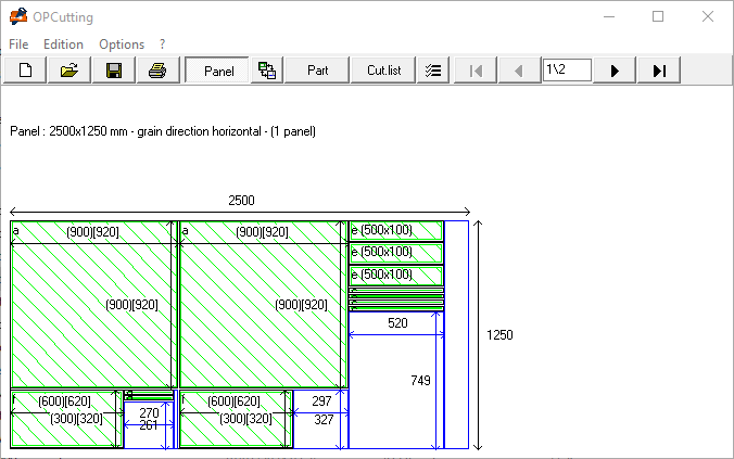
Display a cutting diagram
Display of the panels and the inserted parts:
Once you have determined the band for edges and the cutting thickness and the calculation for the insertion of the parts in completed, the panels will automatically be displayed (if the Panel button on the toolbar is checked) and the first panel of the cutting optimization is drawn with the parts inserted inside.
If the cutting optimization includes several panels, the navigation buttons will be activated and you can:
Display of the cutting lines in panels:
You can view the cut lines in the panels.
1. The Panels button must be pressed, if not click on this button in the toolbar.
2. Click on the Display mode selection button.
3. Click the Display cutting lines option.
Display of the different parts:
Click on the Parts button in the toolbar, the first part of the cutting optimization is drawn.
If the cutting optimization contains more than one type of part, the navigation buttons will be activated and you will be able to see the other parts in the same manner as indicated above.
Display of the cutting list:
Click on the Cut.list (Cutting list) button of the toolbar, the first page of the cutting list, including the characteristics of the various parts is displayed.
If all of the specifications of the parts cannot be shown on only one page, the navigation buttons will be activated and you will be able to see the following pages as indicated above.
Modification of a cutting diagram
Selection of the desired modifications:
1. Click on the Edition menu.
2. Click on the Modify menu, and the Modification Options dialog box opens.
3. Select one or more options among Modify the optimization criteria, Modify the panels, Modify the parts or Modify the bands for edges or the cutting thickness according to the modifications that you wish to carry out.
4. Click on the OK button, the dialog box named Modification Options closes. According to the options that you have checked, the corresponding dialog boxes will open, one after the other, so that you can carry out the desired modifications.
Modification of the optimization criteria:
The dialog box named Modify the optimization criteria will open. You can then choose the desired criteria (see Selection of Cutting optimization criteria).
Modification of the panels used:
The Modify the panels dialog box opens with the first panel of the list. You can modify the features of this panel like those of the following panels or create new panels (see Selection of the panels used).
Modification of the various parts:
The Modify the parts dialog box opens with the first part of the list. You can modify the features of this part like those of the following parts or create new parts (see Creation of the parts).
Modification of the bands for edges and cutting thickness:
The Modify the band for edges or cutting thickness dialog box opens. You can modify these values (see Determination of the band for edges and cutting thickness).
Detailed description and purchase
Deleting a cutting diagram
1. Click on the Edition menu.
2. Click on Delete, and the current cutting optimization diagram is deleted.
Detailed description and purchase
Saving a cutting diagram
1. Click on the File menu.
2. Click on Save. If your cutting optimization is new then the Save as… dialog box opens, prompting you to choose a file name and folder for saving your cutting optimization. If your cutting optimization has already been saved, it is automatically saved in the folder with the previously chosen file name.
Detailed description and purchase
Loading a cutting diagram
1. Click on the File menu.
2. Click on Open. If you were previously working on another cutting optimization, a dialog box will prompt you to save it. The Open dialog box opens so that you can select the cutting diagram file you wish to load, which is then displayed in the OPCutting window.
Detailed description and purchase
Printing a cutting diagram
Printing the panels and the inserted parts:
1. Click on the Pan… button.
2. Click on the Print button, all panel drawings and inserted parts are printed.
Printing the various parts:
1. Click on the Parts button.
2. Click on the Print button, all parts drawings are printed.
Printing the cutting list:
1. Click on the Cut.list button, if the Pan… or Parts buttons are already selected.
2. Click on the Print button, and the parts data cutting list is printed.
Detailed description and purchase
Export a cutting optimization
You can export either the cutting list or the cutting optimization itself (list of panels and parts optimized for cutting). Please note that a cutting optimization exported in this way is intended for import into other applications and cannot be re-imported into OPCutting.Export a cutting list:
Data relating to individual parts of a cutting optimization can be exported in:
Delimited text "; " (txt or csv) or silk (slk, formatted data) for use in spreadsheets (Excel, LibreOffice Calc, etc...), database management software (Access, LibreOffice Base, etc...) or other programs that support the import of data in either of these formats.
The importation of the data of a cutting optimization in an Excel's worksheet will allow for example their exploitation by an Excel application of estimate using a link on this sheet or by making a copy/paste data of this one in another sheet on which calculations are performed.
1. Click on the File menu.
2. Click on the Export menu. The Export dialog box opens.
3. By default, Export the cutting list is selected. Leave this option selected and click on OK button.
4. The Export the cutting list dialog box opens, prompting you to choose a file name and folder for saving your data, as well as one of 3 export formats: txt, csv or slk. Enter the name and folder, select one of these file formats and click Save. The data for the individual parts of the cutting optimization is exported in the selected format.
Export a cutting optimization:
Data relating to the various panels and parts of an optimized cut can be exported in :
Delimited text ";" (txt or csv) for use in spreadsheets (Excel, LibreOffice Calc, etc...), database management software (Access, LibreOffice Base, etc...) or other programs that support the import of data in one or other of these formats.
The information presented in this format can be more easily used in workshops (particulary in certain professional processes).
The first part of the list is made up of panels to be cut and is characterized by a Reference field including the panel numbers and 2 blank fields, Designation and Destination Panel. The second part of the list is comprised of the parts cut and contains in the field Destination Panel the number of the panel from which each part must be cut.
1. Click on the File menu.
2. Click on the Export menu. The Export dialog box opens.
3. By default, Export cutting list is selected. Select the Export cutting optimization option.
4. Click on the OK button.
5. The Export cutting optimization dialog box opens, prompting you to choose a file name and folder to save your data, as well as one of 2 export formats, txt or csv. Enter the file name and folder, select one of these file formats and click on the Save button. The data for the individual parts of the cutting optimization is exported in the selected format.
Detailed description and purchase
Materials management
Add a material:
1. Click on the Edit area.
Delete a material:
1. Click on the material you wish to delete in the materials list, and it will immediately appear in the Edit area.
Detailed description and purchase
Unit of measure management
1. Click on the Options menu.
2. Click on the Unit of measurement menu.
3. Select a unit of measurement, Millimeter, Centimeter, Inch or Meter, this choice determines the unit of measurement used for the selection of dimensions of panels, parts and for the display of these dimensions.
4. Click on the OK button.
Detailed description and purchase
How to use OPCutting to make your cutting optimization
1. Determine the unit of measurement in which you wish to work (see Unit of measure management).
Warning! make sure that you use the same unit of measurement for all of your dimensions and also when determining the band for edges and cutting thickness.
2. Set up your cutting optimization (see Setting up of a cutting diagram) by entering the dimensions and features of the various panels which you have in stock or wish to use, and then by entering the same information for the parts that you wish to cut. Determine the band for edges and thickness of the cutting thickness.
OPCutting determines the optimal way to insert parts into the designated panels and will create new panels if all of the parts will not fit into the designated panels.
3. Print the drawings of the panels and inserted parts (see Printing a cutting diagram).
4. Each drawn panel corresponds to a real panel. Use dimensions shown in the drawings to draw on the real panels the lines of cuts by transferring dimensions. Consider the cutting thickness especially if you did not envisage of band for edges added to the dimensions of parts. Be careful not to mistake you in unit of measurement.
OPCutting makes the creation of a cutting optimization using wood panels easier as well as those using various other materials (glass, metal etc.). It will also help you to save considerable amounts of time and money by avoiding the waste of panels and large amounts of off-cuts that are difficult to make use of.
The data relating to the various parts (the cutting list) can be exported in supported formats along with the majority of spreadsheets which make cost calculations and integrate them in estimates or computations (see Export a cutting optimization).
Detailed description and purchase
Label printing
OPCutting can print labels for each part in the cutting diagram, so that they can be labeled once the cut has been made. A label contains the reference, designation and dimensions of the part to which it refers. Labels can only be printed once a cutting optimization has been created.
1. Click on the File menu.
2. Click on the Print labels.
3. Select the label reference from the References list, or enter the features of a new label if it is not in the list.
4. Click on the Print button.
Adding a label reference:
1. Enter the new reference and label features in each of the fields: Reference, Height, Width, Top margin, Bottom margin, Vertical pitch and Horizontal pitch.
2 Click on the Add button, and the label reference whose features you've just entered will appear in the reference list after the others.
Deleting a label reference:
1 Click on the line that you would like to delete within the list of references. The features of this label reference will be displayed in the corresponding input boxs.
2. Click on Delete button, and the selected label reference is removed from the label list.
Detailed description and purchase
Summary
The summary gives you not only a description of the different panels used, but also their number and total surface area by format (identical dimensions, material and grain direction). It also enables you to display the list of off-cuts, print it out and export it in txt or csv format, which you can then open in Excel and/or integrate into stock management software (after reformatting the columns in Excel).
It gives you:
- The number of panels (by kind of panels).
- The total surface area of panels (by kind of panels).
- The linear cutting (cumulative of lengths sawn by kind of panels).
- The number of parts inserted (by kind of panels).
- The linear field strips of parts inserted in panels (by kind of panels).
- The total surface area of cut parts (by kind of panels).
- The total surface area and percentage of scraps (by kind of panels).
- The scraps rate (by kind of panels).
Copying a summary item to the clipboard:
1. Select one of the panels in the list on the left.
2. Select a summary item from the list on the right. The selected item and its value are displayed in the text boxes in the Copy value to clipboard section.
3. Click on the Copy button. The value is copied to the clipboard. You can then paste it into Excel, Word or another application.
Print summary:
Click on the Print button.
Access to display, print and export the scraps list:
Click on the Scraps list button.
Print scraps list:
Click on the Print button.
Export scraps list:
1. Click on the Export button. The Export scraps dialog box opens.
2. By default, the options defined in the Export scraps options (See Export scraps options) are selected. You can leave these options selected, or modify them as you wish.
3. Click on the OK button.
4. The Save as dialog box opens, prompting you to choose a name and folder for saving your data, as well as one of the 2 export formats, txt or csv. Enter the name and folder, select one of these file formats and click on the Save button. The scraps formats (dimensions, material and grain direction) corresponding to the criteria you have defined are exported in the selected format.
Detailed description and purchase
Import a cutting list
Data relating to individual parts in a cutting optimization (cutting list) can be imported into OPCutting to create a new cutting optimization. This data must be stored in delimited text ";" files (txt or csv) in the form :
Reference;Designation;Number;Length;Width;Thickness;Material;Grain direction (terminated by a line break).
The grain is noted in the form of an integer:
0 for horizontal direction, 1 for vertical direction and 2 for unspecified direction.
By default, OPCutting determines the panel dimensions and material required to cut the imported parts. These default values can then be modified.
You can also generate your cutting diagram from a cutting list created in another software program (quotation software, spreadsheet, etc.), allowing you to export data in text or csv format.
1. Click on the File menu.
2. Click on the Import menu.
3. The Import cutting list dialog box opens, giving you information on the import procedure.
4. Check the box First line of the file contains the headers, if this is the case, otherwise leave the box unchecked.
Please note that if the file to be imported contains column headers and you leave this box unchecked, an error will be generated when you launch the import and the import will be cancelled!
If, on the other hand, you check this box and the file doesn't include column headers, no error will be generated, but the first line of the file will be ignored!
5. Click on the Import options button, the dialog box in which the various import options are defined opens.
Here you can determine the order of the columns containing the various fields required for cutting optimization. Define which fields are to be imported and which are to be filled in automatically by OPCutting.
In this dialog box, you can also select the unit of measurement used for part dimensions in the file to be imported from the Unit of measurement used in the file for part dimensions list.
Caution: if you select a unit of measurement other than the one used in the file, you risk obtaining parts with totally incorrect dimensions.
6. Click on the Ok button. If you have not made any changes to the predefined options, the Import debit card options dialog box closes.
If you have made changes to the predefined options, a dialog box appears, displaying a summary of the import options and inviting you to validate them.
Click on the Yes button to confirm and close the Import cutting list options dialog box, click on the No button to close the Import cutting list options dialog box and continue modifying the options.
7. Click on the Ok button, the Import cutting list dialog box closes and the Open file dialog box opens.
8. Select the file to be imported.
9 Click on the Open button, the dialog box closes and the Modification Options dialog box opens, inviting you to select the modifications you wish to make to the default values given by OPCutting (see Modification of a cutting diagram).
10. Once all changes have been made and the last dialog box closed, the cutting diagram is displayed. You can then save it and make subsequent modifications, just as if the cutting diagram had been created in OPCutting.
Detailed description and purchase
Dimensions management
OPCutting facilitates and accelerates your ability to enter dimensions thanks to its module of management of dimensions.
Set up the lists of dimensions that you have most recently used for your panels and parts. You then can use the Selection of the panels or Selection of the parts dialog boxes to select with only three small clicks, the length, width, and thickness of a panel or a part and then assign these values to the corresponding edit areas as opposed to having to re-enter each of these values.
OPCutting manages two lists of dimensions separately, one for the panels and another for the parts.
1. Click on Options menu.
2. Click on Dimensions Manager menu.
3. Click on Dimensions of the parts or Dimensions of the panels . The Dimensions Manager dialog box appears.
Add a triplet (Length, Width, Thickness):
1. Enter the new dimensions in each zone Length , Width , Thickness .
2. Click on the Add button and the triplet of information will appear in the list of dimensions with the following format: Length x Width x Thickness.
Delete of a triplet (Length, Width, Thickness):
1. Within the list of dimensions, click on the line that you wish to delete. The information from this line will appear in the corresponding edit areas.
2. Click on the Delete button, the triplet of dimensions selected will be removed from the list.
Selection of the dimensions of the panels or parts:
In either the Selection of panels dialog box or the Selection of parts dialog box:
1. Click on one of the edit areas, Length, Width, or Thickness.
2. You can choose to enter a value or to leave the zone blank. Right click with the mouse and the Dimension Management box will open. If you entered a value, then the list displayed will be reduced to lines containing the entered value.
3. Choose one of the triplets Length x Width x Thickness (corresponding to the length, width, and thickness of the panel or part that you are creating) from the list of dimensions.
4. Click on the OK button. The Dimension Management box will close and the values entered will automatically be assigned to the corresponding zone in either the Selection of panels dialog box or the Selection of parts dialog box.Detailed description and purchase
Selection of the cutting optimization criteria
OPCutting will allow you to choose the criteria with which it will choose the parts that must be inserted first in the panels (see Activate the selection of cutting optimization criteria). OPCutting can select these parts based on their surface area, their length, or their width. These criteria can influence the optimization of the cutting and produce different results (more or less panels used), depending of the format and the number of parts to be cut. You can easily experiment with the optimization criteria in order to find the best results for the cutting diagram that you would like. You can also modify the criteria, as well as any other parameter, after having created your cutting diagram.
1. Click on one of the three optimization options:
- OPCutting chooses the parts to be inserted first in the panels based on their surface area.
- OPCutting chooses the parts to be inserted first in the panels based on their length.
- OPCutting chooses the parts to be inserted first in the panels based on their width.
2. Click on the OK button to close the optimization criteria selection dialog box.
Activate the selection of cutting optimization criteria:
By default OPCutting will not display the dialog box of cutting optimization criteria and the default criteria selection will be based on the surface area of the parts.
To activate the selection of cutting optimization criteria:
1. Click on Options on the main menu.
2. In the drop down menu, click on General options and the dialog box will open.
3. Check the checkbox named Modify the cutting optimization criteria.
4. Click on the OK button, and the Options dialog box closes.
Detailed description and purchase
General options
1. Click the Options menu.
2. Click on the General Options menu, the General Options dialog box opens.
Modification of the designation of the objects in which the cuts are made:
By default, OPCutting designates the objects in which the cuts are made as Panels. You can modify this designation to adapt it to your activity.
1. Move to the frame named Designation of the objects which cuttings are be made.
2. Enter the designations, one for the singular and one for the plural:
- Enter a new value for the singular designation in the Singular edit area.
- Enter a new value for the plural designation in the Plural edit area.
Modification of the designation of objects obtained after cutting:
By default OPCutting designates as Parts the objects obtained after cutting. You can modify this designation to adapt it to your activity.
1. Move to the frame named Designation of the objects obtained after cutting.
2. Enter the designations, one for the singular and one for the plural:
- Enter a new value for the singular designation in the Singular edit area.
- Enter a new value for the plural designation in the Plural edit area.
Modification of the maximum length and the maximum width:
You can set maximum values for the lengths and widths of panels. OPCutting only accept values less than or equal to the values defined in the general options, when you enter the lengths and widths of panels or parts. The measurement unit used is the one you defined in the option of selecting the measurement unit.
Enter the maximum dimensions allowed:
- Enter the maximum length in the Maximum length allowed edit area.
- Enter the maximum width in the Maximum width allowed edit area.
Modification of the default length and default width:
You can set default values for the length and width of panels. These values will be populated automatically when creating a new panel. The unit of measurement used is the one you defined in the unit of measurement selection option.
Enter the default dimensions:
- Enter the default length in the Panel Default Length edit area.
- Enter the default width in the Default Panel Width edit area.
Setting the use of band for edge and cutting thickness:
OPCutting allows you to enable or disable the dialog box for entering the band for edge and cutting thickness. It is able to adapt to your business needs and determine default values for band for edge and the cutting thickness. The measurement unit used is the one you defined in the option of selecting the unit of measurement.
Select options to use band for edge and cutting thickness:
- Check the Band for edges and cutting thickness checkbox so that the Band for edges and cutting thickness dialog box is used by OPCutting when you create a new cutting diagram. Uncheck this checkbox otherwise.
- Enter the default band for edge in the Band for edge edit area.
- Enter the defaults Margin for planing in the Margin for planing edit area.
- Enter the default cutting thickness in the Cutting thickness edit area.
Setting the use of grain direction:
OPCutting allows you to determine whether it should take into account the grain direction in order to adapt to the specifics of your activity, or whether it should ignore it. If the panels you're using have a pattern or grain direction, and this needs to be taken into account when cutting the parts, OPCutting will take the grain direction into account.
Check the Grain direction checkbox so that the grain direction selection is active when creating a cutting diagram. Uncheck this checkbox otherwise.
Setting the modification of optimization criteria:
OPCutting allows you to modify certain optimization criteria when creating a cutting optimization.
Check the Modify the cutting optimization criteria checkbox so that the Modify the cutting optimization criteria dialog box is used by OPCutting when you create a new flow rate generating a cutting optimization calculation. Uncheck this box otherwise.
Click on the OK button to validate your modifications and close the dialog box.
Detailed description and purchase


No comments:
Post a Comment